Velomobile design, engineering questions

The part on wich the front linkrod attaches needs to be lenghtend forward quite a bit. It is just a bit of angle Alu. Simple and straight. The pivotpoint on the plate is 90 mm forward of the heart of the strut on the Milan GT, on a Quest this is 85mm. On my Plywood version it is 110mm.

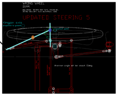
U need to extend the suspension linkrod visualy outward over its pivot point. Then also visualy extend the front linkrod outward over its pivot point. If u draw on 10cm on both that is enough. Just extend in a straight line. The lines will cross, and there is your virtual pivot point. As shown in the video this point moves as the steering moves, but lets forget about that for now. Just with the wheel straight. As shown with turkoise lines.

The line of the suspension link outward is fixed. Difficult to change something with that.

The forward linkrod can be changed. U can change the position of the front pivot on the wheelwell, u can change the position on the plate mounted to the strut. The current position near the suspension strut is way to far rearward. If u move it forward, so there is 85mm between the centre hole and the forward one, the scrubradius will get smaller. Within the width of the strutplate u can also play with its sideways position.

I suggest some backwards engeneering. Draw the zero scrubradius line on the outward extension of the suspension link. Draw the pivot point on of the forward link on the strutplate. Now connect those two and draw the line on, in the same direction, until it hits the wheelwell. There should be the mount to the shell. On the drawing i made the pivot point blue and the forward linkrod mount orange.

On many velomobiles the mounting hole of the rodend that holds the forward linkrod is mounted slightly more outward than both other holes. This gets the scrub radius near zero. A different sollution is to put the mounting point on the wheelwell further back, as is done on the Mango. Both movements alter the angle between the suspension and forward linkrod lines.

My drawing is not as accurate as yours , but to visualize the concept. If u shift the orange point outward, the blue dot will also move outward. If u move the front pivot towards the rear, and do not alter the blue point, the orange one will shift back also.

Ackerman from the blue dot to the rearwheel. That should work out.
 

Anhänge

  • steering.png
    steering.png
    222,1 KB · Aufrufe: 22
Zuletzt bearbeitet:
The part on which the front linkrod attaches needs to be lenghtend forward quite a bit. It is just a bit of angle aluminum. Simple and straightforward. The pivot point on the plate is 90 mm forward of the heart of the strut on the Milan GT, on a Quest this is 85mm. On my Plywood version it is 110mm.

U need to extend the suspension linkrod visually outward over its pivot point. Then also visually extend the front linkrod outward over its pivot point. If u draw on 10cm on both that is enough. Just extend in a straight line. The lines will cross, and there is your virtual pivot point. As shown in the video this point moves as the steering moves, but lets forget about that for now. Just with the wheel straight. As shown with turquoise lines.

The line of the suspension link outward is fixed. Difficult to change something with that.

The forward link rod can be changed. U can change the position of the front pivot on the wheelwell, u can change the position on the plate mounted to the strut. The current position near the suspension strut is way to far rearward. If u move it forward, so there is 85mm between the center hole and the forward one, the scrub radius will get smaller. Within the width of the strutplate u can also play with its sideways position.

I suggest some backwards engineering. Draw the zero scrubradius line on the outward extension of the suspension link. Draw the pivot point on the forward link on the strutplate. Now connect those two and draw the line on, in the same direction, until it hits the wheelwell. There should be the mount to the shell. On the drawing I made the pivot point blue and the forward linkrod mount orange.

On many velomobiles the mounting hole of the rodend that holds the forward linkrod is mounted slightly more outward than both other holes. This gets the scrub radius near zero. A different solution is to put the mounting point on the wheelwell further back, as is done on the Mango. Both movements alter the angle between the suspension and forward linkrod lines.

My drawing is not as accurate as yours, but to visualize the concept. If you move the orange point outward, the blue dot will also move outward. If u move the front pivot towards the rear, and do not alter the blue point, the orange one will shift back also.

Ackerman from the blue dot to the rear wheel. That should work out.
Thanks Low Flyer. That was a very interesting exercise. The language was sometimes difficult. I'll try to find the nomenclature that the engineers use, or that in fairly universal common use and stick carefully to that. So maybe we call the main horizontal strut the "wishbone strut" (Martin Wöllner calls it a single wishbone). The "front strut" for the front link rod will do for now.

I started by explicitly following your suggestion. I chose 85mm between the rod ends for the wishbone strut and the front strut on the steering plate. The projected lines gave a maybe unrealistic rod end position on the wheel well wall.
1711663746736.png

Then I put a front strut with a common looking anchor point on the wheel well and projected to the intersection point (purple). Scrub radius was about 27mm.
Then, for zero scrub radius, I looked at the range of possible front strut variants by simply varying the steering plate length, (the distance dX). I'm digesting those results. The one on the right, I wonder if it is giving enough stability in the X axis (longitudinal). The one on the left, I wonder about the control forces. I went to sleep slightly disturbed about the complexity of calculating the stick forces (control forces).

The longest steering plate was 263mm long
Anyway, I wonder if observation, even of photos, may show that some designs accept a small positive scrub radius. Low Flyer, what were your observations on that? And, what were the conclusions you came to on the effect of positive scrub radius for velomobiles?

1711665951405.png
 
In the two drawings above, the wheel well profiles are not current. The bigger profile shown is at axel height for an earlier, larger wheel diam. The smaller one was at the bottom of the shell. The profile at rod height is probably shifting outboard, so the little short rod at the right may get even shorter.

On my large old workstation (96 GB of cheap DDR3 RAM) there are a large number of web pages waiting to be read or bookmarked. I just noticed this one....
DF steering characteristics (lengthens the steering plate forward)

More reading


For the terms used:

 
Hi @viznz2
You jumped the development of all commonly sold velomobiles with your first post already.
None of the available velomobiles has been completely modelled in CAD. They are all handcrafted. Very well handcrafted but far away from the optimum you could reach by CAD modelling and CFD optimization. They are not even symmetric. The suspension geometry is a result of what could be fitted in the remaining space and a bit of educated guessing and trial an error. I would not search the reason for those strut to axle angles in suspension science but rather what was possible in the remaining space envelope using standard parts like Sturmey Archer drum brakes. Some of the older suspension geometries were reported to react extreamly mean on driver input, bumps, side wind, truck vortizes.

More modern struts stop using the entire drum brake and so can be built much more compact and stiffer, and work well with a 90° strut to axle angle.

I can propose you a suspension geometry (I recently did this for the Bülk) and you can build the aerodynamically and ergonomically optimized shape and internals around it. Straight forward design. It is well known how a good velomobile can be built. Not rocket science (except for the aero) Just none of the successful designers can handle CAD. As simple as that.

And no, nobody ever did an FEA analysis of the composite shells. That would be beyond our financial possibilities. Those are all a result of trial and error experience.
 
I am not an engeneer, so not very familiar with the proper terms. Further more i am writing in a lanauge foreign to me with my scholing in it over 30 years ago. I will follow your proposition.

The range of posible options in your drawings is posible. However the point to wich u draw should be further back, on the line of the middle strutrod. They should go to the point where the centred green line, your measuring start, crosses the contact patch line.

This strutrod is mounted slightly in front of the strut. This slightly in front position provides the caster angle.

A video showing the Quest front suspension in more detail.

Full front end without shell; https://fabacademy.org/archives/2014/students/doutriaux.cedric/mechanical.html

About scrub radius; https://www.carthrottle.com/news/what-scrub-radius-and-why-it-important

On my homebuild, at first i concluded, after milling over it way in to the night like you, that it was to complicated. Then i just gave it a try, roughly building it like the Quest. I have panzersteering and on each a brakelever wich operates that side only. Everything seemed fine on slow test rides. went for a bigger tour and let the VM roll on a slight downhill, reached 50 km/h on a 2 meter wide bikelane. Then i needed to brake so i did. It had way to much positive scrub, so it steered for the grass, beside the lane. It was realy scary. After reading a bit more, including the same DF Tread u linked above, and this one https://www.velomobilforum.de/forum/index.php?threads/evo-k-und-ks-nervoese-lenkung-behoben.38060/
I corrected it and aimed for a slightly negative scrub radius, as Daniel does on his Alpha builds. The Holzvelomobile now steers straight. The negative scrub results in a small force inward, the 1 sided braking results in a small force outward. Both forces are equal, so nothing happens.

The Milan GT has a positive scrub radius, asume about 2-3cm. On the Milan GT, with Panzer steering and singlesided braking also, the lever ratio's are a bit different than on the Holzvelomobile. It has about half the movement on the top of the handlebar part as the Holzvelomobil. The steering is very reasuring, tranquile. Like a well trained German Shepard dog, gently following your lead. That is untill u brake. Then it turns in to a Jack Russel that smells a rat. Suddenly jerking in a random direction.

I realy do not like it and spent about 800km trying to get used to it. I ride mostly flat terrain, with the Milan GT, i ride slower than 50 km/h. Just rolling it steers realy nice, i fully trust it. Even on a slight hill like the 50 meters or so we have here. I get up to 70. I have no problem rolling that speed, but i am scared to brake, cause it just depends wich side grabs first, in wich direction it will steer. Or i need to hold the bars wich much more force than i am used to. The steering when not breaking is much less nervous than i am used to in the Holzvelomobile, realy good. But when braking i am uncertain what will happen, and the resulting changes in direction are not confidence inspiring. I've got the parts ready to change it, like @Marc did. But that is an operation that will take several hours, and i am wrenching outside. So have not done that yet.
 
The Milan GT has a positive scrub radius, asume about 2-3cm. On the Milan GT, with Panzer steering and singlesided braking also, the lever ratio's are a bit different than on the Holzvelomobile. It has about half the movement on the top of the handlebar part as the Holzvelomobil. The steering is very reasuring, tranquile. Like a well trained German Shepard dog, gently following your lead. That is untill u brake. Then it turns in to a Jack Russel that smells a rat. Suddenly jerking in a random direction.
:ROFLMAO:
I realy do not like it and spent about 800km trying to get used to it. I ride mostly flat terrain, with the Milan GT, i ride slower than 50 km/h. Just rolling it steers realy nice, i fully trust it. Even on a slight hill like the 50 meters or so we have here. I get up to 70. I have no problem rolling that speed, but i am scared to brake, cause it just depends wich side grabs first, in wich direction it will steer. Or i need to hold the bars wich much more force than i am used to.
They are much more controllable if you don't start braking softly till the brake pads make contact with the drum, but grab both brakes with some authority and then ease-up till you get the appropriate braking force for the situation. Its very annoying on wet roads and I hated that brake behaviour.
The steering when not breaking is much less nervous than i am used to in the Holzvelomobile, realy good. But when braking i am uncertain what will happen, and the resulting changes in direction are not confidence inspiring. I've got the parts ready to change it, like @Marc did. But that is an operation that will take several hours, and i am wrenching outside. So have not done that yet.
The braking behaviour of my GT is great after the mod, but the steering will get a bit more nervous as a result. I grew accustomed to it and don't think its an issue up to well over 90km/h, side wind gusts or truck vortices. Not necessarily all combined, though...

After a while I've put a M6 nut between the ball head of the steering rod (of the tank steering handle) and the Milan strut, to increase the "lever ratio" and tone down the slight nervousness a bit.

@viznz2 the mods to my old Milan GT Mk2 are described here:
 
Zuletzt bearbeitet:
Hi @viznz2
You jumped the development of all commonly sold velomobiles with your first post already.
None of the available velomobiles has been completely modeled in CAD. They are all handcrafted. Very well handcrafted but far away from the optimum you could achieve by CAD modeling and CFD optimization. They are not even symmetrical. The suspension geometry is a result of what could be fitted in the remaining space and a bit of educated guessing and trial an error. I would not search the reason for those strut to axle angles in suspension science but rather what was possible in the remaining space envelope using standard parts like Sturmey Archer drum brakes. Some of the older suspension geometries were reported to react extremely mean on driver input, bumps, side wind, truck vortices.

More modern struts stop using the entire drum brake and so can be built much more compact and stiffer, and work well with a 90° strut to axle angle.

I can propose you a suspension geometry (I recently did this for the Bülk) and you can build the aerodynamically and ergonomically optimized shape and internals around it. Straight forward design. It is well known how a good velomobile can be built. Not rocket science (except for the aero) Just none of the successful designers can handle CAD. As simple as that.

And no, nobody ever did an FEA analysis of the composite shells. That would be beyond our financial possibilities. Those are all a result of trial and error experience.
Hello,
I'm interested in any advice you have on the suspension/steering geometry. If you'd rather do that with direct contact I will send a DM with my email address.

Gregg.
 
@viznz2 the mods to my old Milan GT Mk2 are described here

Marc,
I almost missed that. I only looked at the first page on the sofa and it is very interesting. Your skills are good. The trailing arm mod info is pertinent. The arm length looks quite short, but I am early days on the subject yet. If it did prefer to be longer, while keeping on the same axis, is there much clearance between the rod end body and the bracket? Looks like there will be.

Gregg.
 
I am not an engineer, so not very familiar with the proper terms. Further more I am writing in a lanauge foreign to me with my scholing in it over 30 years ago. I will follow your proposition.

The range of possible options in your drawings is possible. However the point to wich u draw should be further back, on the line of the middle strutrod. They should go to the point where the centered green line, your measuring start, crosses the contact patch line.

This strutrod is mounted slightly in front of the strut. This slightly in front position provides the caster angle.

A video showing the Quest front suspension in more detail.
It's all good, as the youngsters used to say. I'm just trying to keep to the formal or commonly accepted names and nomenclature.
I am not an engineer either. I was about age 20, at the midpoint of a heavy science/engineering degree, and suddenly all my energy and enthusiasm left. I went to art school instead and was like a fish thrown back in the water. Had to learn some math/physics myself later....

The issue of how to correctly project lines to approximate the trailing arm position for zero scrub radius...I think I get you now. I had some confusion from your first post on that. I may reply again and include a drawing so the question and answer is explicit. Wait until then.

Oh, and Sauki. I have enjoyed his YouTube before. There's something really likeable about him.

Gregg.
 
Mag ja sein, aber bei höheren Geschwindigkeiten ist Hecklenkung m. W. immer noch instabiler -manche Zielkonflikte lassen sich aktuell eben noch nicht auflösen.
Daher ist es m. W. wichtig, vor dem Bau zu wissen, wo die eigenen Prioritäten liegen.
Grundsätzlich hast du wohl Recht, wenn man Geschwindigkeiten über 70 km/h fahren möchte, aber da werden auch manche klassische Velomobile mit Frontlenkung instabil aufgrund Mängel in der Spurenstellung oder Aerodynamik.
 
[...]
1) Suspension/steering geometry.
- Camber
- Caster
- King pin inclination
- Toe in/out.

Are there common opinions about ideal geometry for velomobiles? [...]
Hello Gregg,

I had some information from some older books and some old assembly instructions. One was this, though it is mainly on motor vehicles I found it helpflul:

KFZ FW P92.jpg KFZ FW P94.jpg

The best practice value is give with 0 to 9 Degrees.
It is from this book (If you need help for translation, let me know).

KFZ FW Cover.jpgKFZ FW Biblio.jpg

From this, I chose 8 Degrees for the King pin inclination in my Velocar. Together with also about 8 Degree for the Caster it is able to give a calm steering. Only while braking I have to hold the steering tight.

There is also given a chapter on the Caster, but there is no best practice value given. KFW FW P98.jpg
 
And then there is an old instruction from Werner Stiffel, who has been very busy with HPV things, building recumbent bikes, trikes and more. He sold them, but they where more or less hand made one offs. But he also did a lot research together with others in the 1980s to 2000s on best practices.

And here is his Trike Type 3R4 - I bought these plans some 20 years ago:
Stiffel 3R4 Cover.jpgStiffel 3R4 P10.jpg

For G he first used 18 Degrees and later corrected it to 8 Degrees.

Stiffel 3R4 P16.jpg
So here the angle is 5 Degrees, together with the rest of the geometry, he has an Caster of 40 mm

I hope this old stuff is useful for your plan.

From both of the source there are also Data on the other point of your List 1) given - if you are interested


Volker
 
Zuletzt bearbeitet:
And then there is an old instruction from Werner Stiffel,.....did a lot of research together with others in the 1980s to 2000s on best practices.
And here is his Trike Type 3R4 - I bought these plans some 20 years ago:....................
From both of the source there are also data on the other point of your list 1) given - if you are interested........

Thanks Volker.
I can look for that book online, and for papers by Werner Stiffel...and add that to my meager reading list:giggle:

Gregg.
 
Zurück
Oben Unten