CFD flow modeling for velomobile design/analysis

Beiträge
105
I had hoped that Michael or someone similar who is using modern CFD tools would start this thread, but maybe we just need to start. I have some understanding of aerodynamics but no practice with full CFD. We need one or two people with CFD experience to keep an eye on this thread.

This could be a place to share on CFD applied to velomobile design. Results, notes on the method, limitations, opportunities...

Bt first...(hoooooot sounds)
1663224600018.jpeg
The little icon with the medieval trumpet signals that we should just bring our technical (A-) game and leave our social dysfunction, misgivings and pessimism at the door.

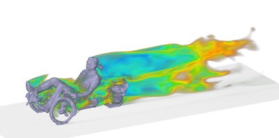
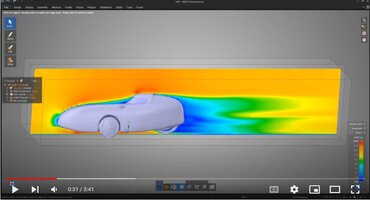
To begin...Just noticed this interesting velomobile CFD sim by Christof Gebhardt (carouso) https://www.e-moped.net/2019/12/07/wie-strömt-s/

A snapshot from the video...
1663224735268.jpeg

Recently discussed here (in the usual diffuse manner)... https://www.velomobilforum.de/forum...aler-windkanal-windlast-auf-velomobile.57642/
After post #14

I find this study very interesting and useful. Well done Christof. And it is really encouraging how blindly fast it was to acquire the model surface, then prep and run the CFD. I was a bit pleasantly shocked..Christof describes "from the 3D scan to the geometry preparation to the result - took about 2 hours"

I'm sure he will answer some questions about how the meshing can be so automatic, or about the analysis tool....

I interpret the "road" as being just a stationary part of the "tunnel" walls. And there looks like no flow interaction with the wheel wells, and the wheels are not rotating. But, two hours..!

So my happily naive instincts tell me that a more detailed model with moving road and rotating wheels, maybe even realistic internal flow...could be legitimately within reach for a small indie velomobile design exercise.

Returning to the video of Christof's flow sims. I don't believe that a more explicit model will change the observations I'm about to make very much. And these thoughts, with a little familiarity with aero, are fairly obvious. Even with uncertainties, one can learn much...

I snapped that screen shot because it was a fair illustration of what I thought it was telling me. I think colors in the video are always showing the relative velocity. This dark blue shows V=0 or close to it. The "separated" volume behind the body is quite large. I'm guessing it contains an unstable system of vortices that keep shedding.

The streamlines that I saw enclose that separated volume. Someone with more experience may know if the spiraling streamlines are a sign of the shedding vortices, or somehow caused by the shape of the rear of the body. I can't change my view to see if there are symmetric left and right spiraling streamlines.

Ideally, the afterpart of the body should manage the pressure recovery and separation should occur at the trailing edge (TE). In the sim, the flow is separating from the surface well before the TE. Look at time 03:21 where a vertical slice showing velocity distribution shifts laterally and you can see the extent of separation.

To be clear, any blue air is almost stationary in this virtual wind tunnel. In real life it is being dragged along with the body. For less drag, minimize that. The shape of the whole body plays a part in this. The way that pressure gradients over that shape culture the boundary layer (BL).

The other two obvious areas with V=0 are the stagnation point at the nose (file that for a separate optimization issue) and the base of the windscreen. The flow is not happily traversing this abrupt curvature or break. You can see from the V distribution, the likely shape that it would prefer to flow over.

Because the canopy shape (fairing over the pilots head) is tallish and narrow, the streamlines tend to go around rather than over it. So it could have a shape that allowed that better. And or bigger fillets all round that shape.

Some residual thoughts after this...Maybe there are a few people with interest, skills and access to FLUENT (ANSYS now own FLUENT) and the machine time is not as long as some (including me) fear. Maybe some studies can even be done on a free student license. There are definitely a lot of people with skills to produce the surface definition.

The issue remains, where best to direct this energy. I am not in favor of doing a lot of comparative studies on the existing velomobiles. I'm interested in new ideas, and one or two of the existing bikes. Most interesting existing velo is the Go One Evo R. And the new Bulk. They are both careful refinements of almost opposite ideas.

I believe that sofar velo designers are a bit careless about the boundary layer. But imagine a version of the Evo R that could keep laminar over 60% of its length. It will gain a little frontal area doing that, mostly to enclose the wheels.

Gregg....
 
Zuletzt bearbeitet von einem Moderator:
An interesting idea and potentially very useful CFD sims project came up on the ......
https://www.velomobilforum.de/forum...analysis-experiment.67345/page-2#post-1486068
(page 2)

The canopies for the GO One Evo R, are described as having variation in shape which leads, anecdotally, to winning/loosing races. The canopies are described as being heat formed with air pressure, without a mold or form. Separately, a paper on boundary layer transition on glider canopies, using oil flow visualisations with CFD and wind tunnel, looking at transition from leakage and gaps.

The Evo R, variation in shape and treatment at the canopy edges, gaps, may give rise to large differences in the area of laminar flow.
My guesses on transition zones post #32. Some quick thoughts re a study on this with CFD at post #37

Gregg...
 
(Somewhat off-topic) Question: Are 2D CFD analysis of the "center slice" even valid on a VM?

The analysis above is a 2D slice of a 3D analysis so that is definitely valid, but often only a 2D analysis of the center slice is done (probably due to resource constraints). On a car that is probably very valid, as the geometry does not change to drastically between the center and "somewhat off-center" slices. On a VM that is is not really the case and a slight deviation from the center slice will have a significantly different geometry.

Is that a problem? :unsure:
 
at sub
Re the visualisation using slices from the 3D CFD analysis. Those simple slices are used because they are, I assume, easy to have. Watching a stack of slices animate sideways one can build a mental picture of the 3D, but one has had a look "inside". With the streamlines one has a more literal view. The streamlines seen in the video will have been done using some easy to set up or automatic options. I'm assuming/hoping that with the post processor tool, extracting data from sim result files you could stack up an array of streamlines anywhere you want. With 3D panel sims this was easy 15 years ago, so I assume it also is easy with full CFD.

Re using a 2D analysis to make inference about the behaviour in 3D. I have only done this with relatively simple shapes. A sailplane pod is a very refined, sophisticated surface, but is in a sense very simple. Viewed from the front, any "slice" should be orthogonal to the surface (look like radial lines). One can curve the plane of the slice to follow the streamline.

For this process I have used 2D panel codes Xfoil and PANDA. PANDA from Professor Kroo at Stanford, was good for shape exploration, an effectively instantaneous inverse design tool. Xfoil (from Prof Drela at MIT) was a more refined analysis, but still very quick. A run for an array of alphas took about 2 seconds on the Z800. (I discovered last night that I do have a version that runs on 64 bit Windows, I'm very happy). Further, with Xfoil one can use a precise inverse design process, specifying the velocity distribution and Xfoil calculates the surface. One can also do this over just a part of the surface, redrawing the surface with the curser (mouse). I found this very useful for intuitive optimisation.

The Evo R is a shape where one could learn something about the characteristics of the shape of the upper body with these methods. The degree to which the shape allows laminar flow, and why, will be obvious from the pressure/velocity gradients.

Gregg...
 
A sailplane pod is a very refined, sophisticated surface, but is in a sense very simple.

Yep, it might be symmetric around the roll axis which would make 2D analysis feasible again. I am more worried about VMs not having roll-axis symmetry, nor a shape that is relatively constant along the pitch axis. In other words it is not really possible to cut any 2D slices that would have a similar profile if shifted slightly.

Xfoil (from Prof Drela at MIT)

Xfoil really is a gem of a free software. I used it some time ago to optimize the blade profile for a small backyard vertical-axis wind turbine (VAWT). Xfoil is actually fast enough that I could run the whole program (without GUI) from Python and do the the optimization with scipys optimization toolkit.

There is a great episode of the OmegaTau podcast where they discuss how they did that on the MILAN airplane: https://omegataupodcast.net/371-automatische-profiloptimierung-und-milan/ (in German think). (Obviously that is where I got the inspiration to try that myself)
 
Yep, it might be symmetric around the roll axis which would make 2D analysis feasible again. I am more worried about VMs not having roll-axis symmetry, nor a shape that is relatively constant along the pitch axis. In other words it is not really possible to cut any 2D slices that would have a similar profile if shifted slightly.
Do you mean rotational symmetry about the roll axis? Most sailplanes look like modified ellipses in section, and the locus of the ellipse centers is not a straight line. Doesn't matter. If one could make a curved plane that is close to the streamline and extract coordinates from that...But commonly I just project onto a flat plane.

One can learn something of the characteristics of the type of shape, but normally not explicit, precise, information for the actual surface. I just did some runs for a shape representing a streamline about 50mm above the wheel arch on an Evo R. Notes on that on the Applied Aero thread. Discus there if you want.

Xfoil really is a gem of a free software. I used it some time ago to optimize the blade profile for a small backyard vertical-axis wind turbine (VAWT). Xfoil is actually almost enough that I could run the whole program (without GUI) from Python and do the the optimization with scipy's optimization toolkit.
I was fairly primitive and intuitive. One has a sense of how to change the velocity profile, so one does that graphically, drawing on the screen with the curser, and xfoil solves the inverse problem, giving the new profile. I realize I didn't express that correctly previously.

Xfoil used to be quite expensive, from Analytic Methods. I had just got a pirate copy and suddenly it was made free. Luckily so, because the manuals etc made a huge difference.

Gregg....
 
Zuletzt bearbeitet:
Hi Gregg, the video you saw was a project for an afternoon. Mainly driven by the opportunity to check the workflow. After presenting it in this forum, there was an idea to compare different existing VMs, but we didn't manage to meet (nearby Munich) and to scan them. After some time, I did a similar scan and exploring simulation for an unfaired trike, but that was the end of my journey. Mombi13.jpg
Of course this simulation has limitations - as always. It is just a model. And the motivation and questions you want to answer, define how you need to model the details. Yes, there are no rotating wheels, no moving ground, the geometry is coarse (it is really hard to get any CAD data, especially reasonable modeled data), the simulation approach is focused on design exploration not maximized fidelity (Ansys Live Solver vs. Ansys Fluent Solver). But I am a big fan with starting with simple models and refine them step by step afterwards, because even coarse and simplified models may provide some useful insights for much reduced costs. In a perfect world, you would do both - simplified approaches for an early identification of the right design direction, combined with following high fidelity simulations on pre-qualified designs.
BTW: Do you have CAD data? Non tesselated? And parametric, to do design changes? That would be a dream. For me, this was one of the show stoppers. Look at the trike model. With my 3D scanner (an add on for an ipad, https://structure.io/), I was not able to resolve more details. And if you want to do changes, based on a tesselated geometry, that's really hard to manage (but on the other hand, the variation often drives the insights). So a good geometry model in my opinion is the basis for variation and understanding.
 
......I did a similar scan and exploring simulation for an unfaired trike, but that was the end of my journey.
1663815573652.png
This is a very cool picture. I would have stolen it to start this thread.
From this sim' I get the feeling that an internal flow model might be feasible. A realistic arrangement of forms (approximate forms, ignore surface textures) inside the shell. Realistic entry and exit ports. Ability to include some internal ducting, and NACA ducts at the surface. Externally, no wheels, or wheel wells, no road...

...the simulation approach is focused on design exploration...starting with simple models and refine them step by step afterwards, because even coarse and simplified models may provide some useful insights for much reduced costs. In a perfect world, you would do both - simplified approaches for an early identification of the right design direction, combined with following high fidelity simulations on pre-qualified designs.

This is exactly my philosophy from when I was using 3D panel flow sims and structural FEA...

If I described my 2 basic projects...
Beginning with a body similar to the Evo R.
Using simplified CFD for analysis, and only intuitive optimisation.

Project 1) with open wheel wells.
- Extend laminar flow on the upper body. (flow above the wheel wells...modeled without wheel wells)
- Minimise the drag due to interaction between the surface streamlined flow and the wheel wells.
- Intuitively optimise bottom shape and interaction with wheel wells.
- Intuitively optimise the traverse across the wheel arch...body-gap-disk-gap-body.
- Examine the BL after reattachment at the rear of wheel well. How then best to manage the pressure gradients?
-Refine the closure at the tail, with exhaust vent (include approximations on vent flow)

Project 2) with closed wheel wells. (body width for wheels at max steering lock)
- Extend laminar flow on the whole body. One assumes a trade off with body width as the transition point is shifted rearwards. Coeficient of friction (Cf) reducing and coef of pressure (Cp) increasing.
- Intuitively optimise bottom shape and interaction with wheel wells.
- Ditto as project 1) on closure and exhaust

Project 1A) and 2A), as above but wider track..
maybe talk about that later.

BTW: Do you have CAD data? Non tesselated? And parametric, to do design changes? That would be a dream. For me, this was one of the show stoppers. Look at the trike model. With my 3D scanner (an add on for an ipad, https://structure.io/), I was not able to resolve more details. And if you want to do changes, based on a tesselated geometry, that's really hard to manage (but on the other hand, the variation often drives the insights). So a good geometry model in my opinion is the basis for variation and understanding.

Now for the bad news. I'm not using any normal surface or solids code at all. I have been dormant for years and before then I never made the leap. I think the most powerful thing for me to learn right now (that's accessible) is Rhino 3D. So I will begin immediately.

Tessellated meaning meshed surfaces? Not yet. The old model builder code Loftsman that made meshed surfaces for 3D panel code CMARC-12 is too slow and I don't yet have my 64 bit update. But Rhino should give anything.

Parametric. I will research what that is :) I guess it means, in the ideal version, that if I changed a splined moldline in a 2D drawing, the 3D surface model changed by that, and the mesh also. Like that, or just changing the fineness ratio (width/length) and a new mesh is made?

I'm glad you found your way here. I think Michael (mrue) will come also, when he gets less busy.
I will send you a direct message with my email.

Gregg....
 
Hi Gregg, yes, with tessellated I meaned meshed, typically with triangels. That's something I would like to prevent, the meshed geometry is - at least to my experience - not very handy for downstream processes. Yes, parametric means, you have numbers that drive the design and as you change the numbers, the shape changes as well. I don't know Rhino, I use Creo mostly and earlier a bit SolidWorks and Inventor.
Some new vendors provide online versions and education access free of charge (e g onshape), perhaps that's an alternative?
Best regards
Christof
 
(forgot to press the answers button after I wrote)
I was normally making rectangular mesh cells with Loftsman, but I think it can export STL files. My guess is that Rhino 3D will be worth the effort. It's used for surfaces by a lot of professional designers (or used to be), less so by the design engineers, who normally used SW. I think Rhino is still being developed. Fairly cheap licence, and I may have an old copy already. I think one of the developers lives here in Auckland and runs courses.
 
My guess is that Rhino 3D will be worth the effort.

I can recommend Fusion 360 for CAD ... it's free(-ish) for private (and even low-income professional) use. And from what I heard they somewhat care about the maker community ... probably because it is free advertisement for them. It is surprisingly full featured for something that is basically free to use, even including CAM, CFD and generative design modules.

(caveat: I am definitely "locked" into their product by now and it would take me to relearn something else, but I try other CAD programs once in a while and F360 is just pretty good in comparison)
 
Open wheel wells, flow across, flow in and out.

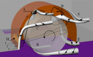
I started looking at the references for automotive wheel wells from beate, post #6 in the Applied aero for velomobile design thread, and the picture...
1664446785738.png

Immediately one thinks that for a VM some structured but perhaps unsteady vortices probably exist, but with a narrower well and skinny wheels it may have very different forms. So I don't know if we can look at the forms in the CFD visualisation and just immagine modifications of those for the VM case.

One of the automotive CFD studies simplified the car body geometry to a box with rounded corners. We might explore generic principals doing something similar for the VM, but the significance of the changes caused by the body shape are as yet unknown. Variations in body shape and its relation to the wells may give very different forms to the airflow at the wells.

Is there a way to learn more about this for the VM case using CFD? Can the more rapid Ansys Discovery tool (or something similar) help?

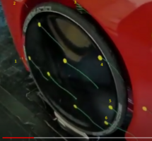
Referring to Leiba record test in the wind tunnel 1 video...
(....https://www.youtube.com/watch?v=wStKr1gBvPU&t=16s....) avoid the ....), it's just added as I have not mastered the link tool.
Looking at 0:16 - 0:26 (I think the later pass by the wheel with the camera operator approaching from the front should be ignored).
1664446674818.png

Sorry for the small numbers....
Streamline #1 is steady and bridging straight from body to disk. Numbers 2,3,4,5 are all showing steady flow inward to the well. Number 6 shows unsteadiness with little movements as it bridges to the body. If it's in or near a rotational flow field that field would have a very thin section.

If we had a moving road and rotating wheels, would we get a system of twister vortices like in the CFD visualisation above? I'm leaning to a no feeling. A VM has a relatively tiny section round tyre with a tiny contact patch, compared to the wide, flatish auto tyre. Less obvious for now is the way the inner face of the VM wheel gets the air rotating.

So if there are simplified ways to show the behaviour of the wheel wells with CFD it would be like mana from heaven....It could lead quickly to ideas for a big drag reduction.

Returning again to the flow from body to disk to body. The way that it separates and reattaches at the gaps..I don't assume that all VMs will have flow looking the same as in this, but it is a useful reference point. I'm itching to know the state of the boundary layer. Is it being sucked into the well? I always assumed that air arriving at the disk would be turbulent. Detail of the traverse over tyre/rim/disk edge probably shows a little valley that could cause transition to turbulent BL.

And the most interesting question, what is the state of the BL after flow reattaches to the body? If one knew, it might suggest some idealised pressure distributions downstream.

Gregg...
 
Zuletzt bearbeitet:
Side note: I just learned that F1 teams have (a) a limited CFD "computer time" budget and (b) are not allowed to use GPUs to accelerate CFD analysis (source, not a good one tbh).
 
My mind keeps returning to how good the flows over the open wheel well looked in that tunnel test
1665206400041.png
(bigger photo and reference previously shown). It's nothing like what we assume from the info about cars we see. In KYLE.ENGINEER's video on the air curtain, the CFD model of the unmodified car shows low V air exiting the well, which forces the stream from the front out from the body. maybe on examination there are well defined vortices with animal-morphic shapes like in the picture beate posted.
1665206600247.png
...https://www.youtube.com/watch?v=ptNnbB7R3SE.... (ignore the ....I keep forgetting how to paste the link as plain text, and telling it to do that fails)
See at 3:38.

One thing I'm sure off, but must confess I'm still guessing...With a car the wide tire and wide contact patch cause a lot of movement just in front of that patch. What it referred to as "jetting", can't remember. Looking at beate's picture again, it's I think what creates vortice system A. On a VM, with the tiny contact patch this might just not happen.

I think somehow we need to go forward and learn more about this. If the time/resources/skills aren't available right now to use CFD for that then one could do some experiments.

- Without wind tunnel. Tufts the perimeter of the wheel arch. Tufts at the front edge could extend slightly into the gap and show if there is flow into the well. Tufts at the rear will show if there is vorticity. Special interest near the bottom. We need more tufts than in the Leiba record test. Maybe some thought and reading up on the ideal tuft thread thickness. Can it be finer? . A gopro sized camera rigged just back a little from the rear of the well and about 500mm off the body. A nd a totally still day, willing players etc.

- In the wind tunnel. Re do the original experiment, with more tufts. I think it may be possible to rotate a wheel. Can a small motor with drive wheel onto the tire be an acceptable penalty? Maybe something else. Will have to save the moving road for later. My thoughts on the relative significance of the skinny VM tires are above.

I have said before and will re state here. I believe that a moving road model scaled down would be feasible unless the change in tunnel turbulence was a problem at the higher speed. Building the scale moving road model and the VM model(s) would yield to some co-operative effort and sharing of expertise. But there may be a hidden snag. Maybe Jan or some one else who knows that tunnel can speak.

Some other thoughts on really useful experiments that could be DIY I will post separately..

Gregg....
 
Side note: I just learned that F1 teams have (a) a limited CFD "computer time" budget and (b) are not allowed to use GPUs to accelerate CFD analysis ( source , not a good one tbh).
I was reading about that somewhere. I wasn't sure how that would be monitored. Engineers spend a lot of energy trying to bend, break or circumvent rules.
 
I can recommend Fusion 360 for CAD ... it's free(-ish) for private (and even low-income professional) use. And from what I heard they somewhat care about the maker community ... probably because it is free advertisement for them. It is surprisingly full featured for something that is basically free to use, even including CAM, CFD and generative design modules.

(caveat: I am definitely "locked" into their product by now and it would take me to relearn something else, but I try other CAD programs once in a while and F360 is just pretty good in comparison)
I haven't looked at them yet. I want to. At the moment I am trying to avoid spending money. I realized I had an old copy of Rhino 3D (3.0) and if I knew how to use it would do all I need. My friend urges that I learn Onshape, which is free. I loaded the lofting lines of the latest shape into Onshape, which was about to get started when I realized that all files in free onshape are public domain. So, a hasty delete and retreat.

I had crafted the lofting lines...top and bottom body lines, maximum but line, and a few critical sections in 3 space in Nanocad ( I had Autocad until the 64 bit switch). Those opened in Rhino and I was able to make a nurbs surface over that in a few minutes (few seconds plus a few minutes stumbling around. Not fully smoothed yet. And I'm not rendering well yet, so the mesh is the best guide .
1665208983127.png
There's a lot for me to learn with Rhino. It could also do all the solids modeling I need as well, so it's attractive. The "designers" vs the design engineers will argue.

Thoughts on inexpensive ways to get into full CFD in another post.

Greg...
 
Inexpensive ways to get started with full CFD

Back in the day, inexpensive and CFD were obviously contradictory notions. Before I wandered away from aero about 13 or more years ago one could sense changes coming...some simulation methods that used to be the provenance of academics and scientists, were being reformed into tools very easy to use. Solidworks had COSMOS FEA and a CFD module. I remember Dr Hanley (Hanley Innovations) had a full CFD code with modeller that was aimed at aircraft designers, much cheaper than FLUENT, and easier to use.

So while I wasn't paying attention, the changes happened. I don't know if there is an eventual democratization, or if it's just a swelling volume of cheaper and cheaper units. The FLUENT owners have a little island in the middle, the price is still high, with a captive market that can afford it.

Ranting over...What are the ways...?

1) open foam. When mrue surfaces I hope he can give some insights into how long it takes to learn.

2) Borrow time on someone else's FLUENT license.

3) FLUENT student license. Free to students. think it has limits on mesh elements, maybe other limits.

4) Discovery? Still trying to understand what it is, whether they give it with Workbench, whether it is a simplified FLUENT...maybe Christof ( carouso ) can tell us.

5) Low cost entry level CFD codes like MicroCFD (3 months USD90). I say entry level but that's just a reference to their market position. I'm not able to compare it to FLUENT or Open Foam. My guess is that some of these codes will be amazing value for money.
If you know one of these put a link in a reply to this post (maybe explore some facts about it first).
So starting a list of those...
- MicroCFD ____ http://microcfd.com/software.htm____
- Fusion 360 has a CFD module (suggestion from fho above). I haven't looked yet.

Gregg....
 
Zuletzt bearbeitet:
Hello Gregg, I sent you a message proposing a phonecall via WhatsApp. If you didn't receive it, you might use my contact information from www.e-moped.net.

Best regards
Christof
 
Zurück
Oben Unten