Eigenbau XYZ Spaceframe vehicle

Hello Hein, Titan Wolf, trike like (Martin?) And Stephan (shs2_de)

It's been a few weeks since I've been able to say what I've done with the idea of a tiltable space frame trike, and I have a few things to share. I have built another new prototype tilting mechanism and have already developed a new version. Interestingly enough, my latest designs are very similar to what Stephan (shs2_de) worked on at the beginning of this forum. It might be interesting for Stephan and others to see a modification of this suspension system. I've also spent a considerable amount of time with my husband and a friend remodeling our 2 bathrooms as well as working overtime & sigh real life & enough said on this subject.

Before I move on much, I would like to address a few comments from Wolf. I read your comment on road obstacles and thought about tilting and locking the tilting mechanism. At first I think that a tipping trike (1st test geometry) for the driver with holes and bumps is actually more level than a non-tipping trike. This is not to say it will not be any smoother ride without shocks, but I believe it will not tip the driver but lift them up and down due to the tilt geometry. The effect is contrarily intuitive, but I believe it is true. The impact on steering will be nothing more than what would happen to a bike. Although I have to admit that it will be different than a non-tilting trike. Secondly, I believe that you are right, that at best it would be a bad idea to be dependent on a locking mechanism that focuses entirely on the stability of the tilt. I really did not want to give you the impression that a tilt lock is the only stabilization mechanism I had in mind. I can see how that was my impression. I've known for some time that the suspension needs some kind of active system to create a roughly centered riding position on a straight road. The active system I am thinking of is a triangle of shocks and springs. This mechanism would tend to provide an upright posture on a straight ride. Last but most important, how do you stop leaning in the wrong direction on a bend? I think, part of the answer is shocks and feathers, but I do not want to rely on that alone. I think tilting requires direct driver control over tipping, not just a tipping lock, and I worked on it and looked for that solution. I think that I have found this solution and I believe that the XYZ framework is well suited for this particular solution.

At this point I would like to insert
a disclaimer. I have no really original ideas in this area of endeavor, but I assemble those designs from others with my own thoughts on how they should work. Hopefully it will get a tip-trike running. I do not claim these devices as my original work, but stand on other shoulders to reach my top shelf (LOL .... to make a phrase).

I insert this disclaimer because I have found something that seems like an original and quite brilliant idea of Martin Hill from Australia. You can watch his work on You Tube while it is available at
verfügbar ist


In short, he seems to have solved the question of how to control a tilting tricycle mechanically during steering. Martin has several video works on his EATSRHPV trike that are very instructive! I will not try to print pictures or make drawings of his prototype. I really do not think I can live up to that. I leave the viewing and analysis of this information to those readers who so desire. I'd rather talk about using his idea and about how I think

So I realize that I have not yet said exactly what makes this wonderful idea of Martin's; if You Tube did not let the cat out of the bag, I'll go into that section in this paragraph. Martin has combined the steering with the tilting technology in a single handlebar package. Sounds a bit strange, I'm sure, but that's exactly what he did. By connecting the handlebar with the tilting mechanism, the handlebars tilt simultaneously with the wheels. He used what Trike Like called "push rod steering" to control the wheel control that was attached to the tilting handlebars. In this way he can control the tilt and the turn at the same time as they are a system in his hands. Wolf this literally uses muscle power, to stabilize and control the inclination * not a brake *. It is not a direct proportional relationship between inclination and cornering, but rather the use of muscle, memory and judgment to determine the inclination. Direct proportional tilt would not work as the degree of tilt changes with speed (originally, I intended to make a blocked proportional tilt). So we use the most advanced computer in the world to control the trike ... one person. The inclination may be more or less depending on the speed and degree of rotation. In the end, it is a metastable system like a bicycle. The faster it gets, the more stable it gets. The slower you can the more unstable it becomes and thus a tipping lock is probably necessary. With a tilt lock the whole trike can not be tilted in no time. The rest of the time on a "normal" slow ride will remain stable. If you doubt, watch the videos! I think his trike is stable even at a stop, but I'm a bit conservative in my judgment until I've built a trike.

Hein, yes, the tilt may actually have to be blocked in very tight turns if it can not be held by muscles in the correct orientation on the turn. Please do not turn around!

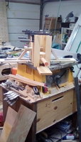
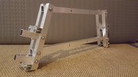
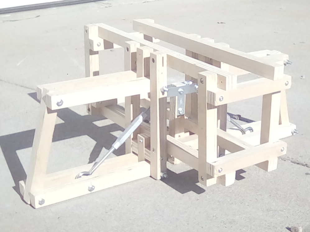
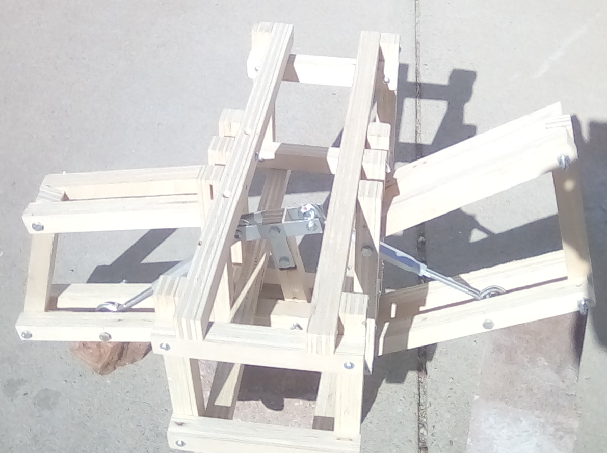
I enclose some pictures of my latest prototype based on a trike called Tripendo and a surprising number of other trikes. The model has the same geometry as all other models. It allows the illustrated turnbuckles to be replaced with shock absorbers and springs to allow tilting and full suspension travel (the turnbuckles are not strong enough so that the inclination is not equal).

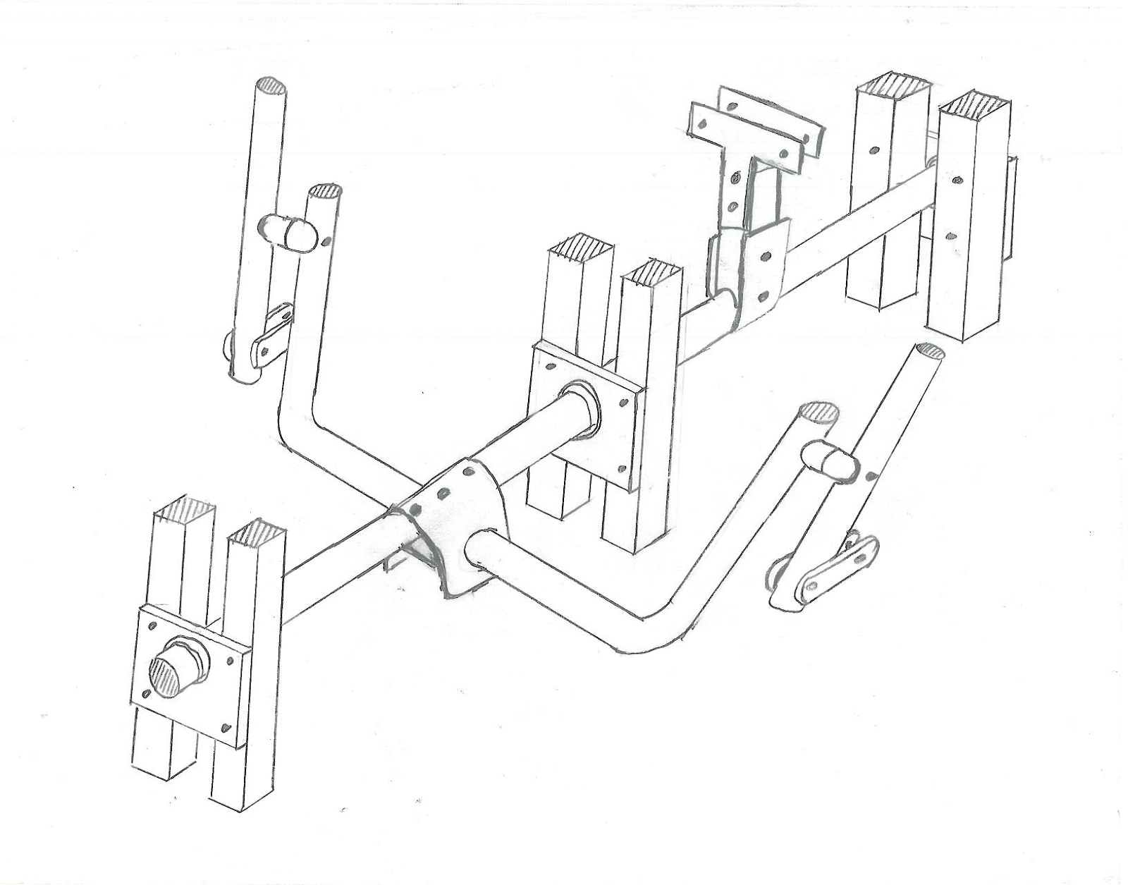
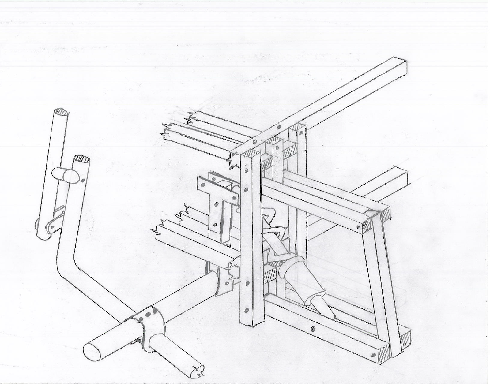
I also attach some sketches. The first should show the connection mechanism between the dump wheels and the steering column in an XYZ trike. The second sketch should show how the tilting steering column and the paddle and joystick steering (push rod steering) generally work together. I did not try to illustrate how the shortcuts work. If you want to see these links at work, go to You Tube. Unfortunately, I have to rebuild the toilets. Ta ta for now Ceeann


As usual (if I have no technical difficulties) the American version can be found at https://dichotomyone.blogspot.com/2018/02/recumbent-tadpole-trike-posts-on_26.html .

Translated with www.DeepL.com/Translator
 
Tilt%2Bsuspension%2B1a.png

Tilt%2Bsuspension%2B2a.png


trike%2Btilt%2Bsteering%2B2.png

trike%2Btilt%2Bsteering%2B1.png
 
Moin!

Brilliant things very often are kept very simple.

"Leave it to us engineers to design the simplicity out of it!" ;-)

That's a comment the physicist Stanley Hooker, who was enthusiastic about the billiance and simplicity of the newly invented jet engine, received from an engineer who had more of an eye for the practical aspects.

Hooker's autobiography has the title, "Not of of an Engineer" :)

Regards,

Hein
 
Hi Ceeone,

The active system I am thinking of is a triangle of shocks and springs. This mechanism would tend to provide an upright posture on a straight ride. Last but most important, how do you stop leaning in the wrong direction on a bend? I think, part of the answer is shocks and feathers, but I do not want to rely on that alone.

Springs certainly can help controllability, but one thing to keep in mind is the possibility of control flutter.

Even the highly professional author of blog http://lefthandedcyclist.blogspot.de/ got bitten by that once ... sudden and total loss of control. No injuries fortunately, but it was "back to the drawing board".

Of course, he had used a spring-assisted leaning system in combination with rear steering, which probably raised the difficulty level quite a number of notches!

Regards,

Hein
 
Hello Hein, Titan Wolf, Stefan and Trike like!

I've done some stuff in the last few weeks that I want to share. I recently posted some sketches that showed that I thought a possible tilt steering mechanism might look like. After reviewing the ideas and models I had previously made, I created the following models. The first is the basic geometry of a tiltable assembly with home joints (rod ends) for the bearings. Home joints are a bit of a departure from what I've illustrated, but in some ways seem to be superior to thrust bearings. I have dust covers for the bearings, but they are not in place ...

Tilt Arm 1.jpg
Tilt Arm 2.jpg Tilt Arm 3.jpg Tilt Arm 4.jpg Tilt Arm 5.jpg

Without the reinforcing structure necessary to hold the arms in place, as my previous post shows, the tilt mechanism will fold well beyond the extreme limit that could be used when tipping on the trike. I just show this to illustrate the potential. The ultimate practical incline would be about 45 degrees on a trike like this one.

I had to experiment a bit to be able to fold everything correctly. I still use 1 "square wood dowels to build the prototypes, and the hardware took a while to get through a slow shipping order from Speedway Motors, see https://www.speedwaymotors.com/QA1-GFR6T-G-Series Rod End Stainless Steel 3-8-24 RH Female Thread, 261549.html

I have used the female rod ends to simplify the possible attachment to aluminum with stainless screws. Above, I still use the published XYZ trike proportions on the main frame. This will change to accommodate the tilt steering column, which you can see in the following videos.

As I wrote earlier, Martin Hill came up with the idea of building a tilting steering column. In the videos I'm posting now, I'm putting this idea on the XYZ platform.

The videos are not working ... sorry. I will post these from YouTube as soon as I can get them to work there...
1st Video here...


This first video shows the test bench that I have assembled to adjust the height of the steering column and the width of the rocker arm arms. This adjustable bench was a great help to make the mechanism work properly. Now here's the second video that has a bit better lighting to see things that work.

2nd Video here... sigh!

That's me with the little ring. I am in junky work clothes. As you can see in the video, the test bench is a bit tipsy if it is not clamped on a bench. I think this illustrates that the tilting mechanism can exceed the theoretical limits that a trike might need to bench press in a curve.


The diagonal bars would be replaced with a similarly sized bicycle rear-wheel shocks. The arms would be completed like the first series of images and have upper and lower sets of arms connected to the outer part of the arms where the wheels would be mounted.


Below are some stills of the mechanism and incidentally the test bench.


Tilt still 1.jpg
Tilt still 2.jpg Tilt still 2.jpg

As you can see, the garage business is very crowded! I'm working slowly to remove garbage ... Finally a picture of the test bench with the oversized shocks, which I bought first. It gives a glimpse of what the final product might look like, although the above images are the revised version and it is already outdated.

IMG_20180421_101719 (1).jpg


So there's a working tilt mechanism that can be controlled. It will make the curves with the full possible tilt.
I believe that this addresses both control issues and feasibility.

Ceeann

As usual the American version will be at https://dichotomyone.blogspot.com/2018/04/recumbent-tadpole-trike-posts-on.html
and the videos are not working there yet either! Darn it!

PS. We now have a working bathroom with toilet, sink, bath and shower. We are about half finished with this task ... continue to the master bath!
 

Anhänge

  • Tilt still 1.jpg
    Tilt still 1.jpg
    122,8 KB · Aufrufe: 185
I have used the female rod ends to simplify the possible attachment to aluminum with stainless screws. Above, I still use the published XYZ trike proportions on the main frame. This will change to accommodate the tilt steering column, which you can see in the following videos.

As I wrote earlier, Martin Hill came up with the idea of building a tilting steering column. In the videos I'm posting now, I'm putting this idea on the XYZ platform.

So hopefully the Videos are now working...


This first video shows the test bench that I have assembled to adjust the height of the steering column and the width of the rocker arm arms. This adjustable bench was a great help to make the mechanism work properly. Now here's the second video that has a bit better lighting to see things that work.

Ok I got one to work... so I will go down a little and add the next.
[DOUBLEPOST=1524400538][/DOUBLEPOST]This first video shows the test rig I threw together to allow adjustment up of the height of the steering column and of the width of the tilt arms. This adjustable test stand was a huge help in getting the mechanism to work correctly. Now here is the second video that has a bit better lighting to see things working.

[MEDIA = youtube] 19IxiOztNgI [/ MEDIA]

Thats me with the pinky ring. I am in junky work cloths. As can be seen in the video the test stand is a bit tipsy unless clamped down on a bench. I think this illustrates that the tilt mechanism can exceed the theoretical limits a trike might need for banking in a turn.

The diagonal rods would be exchanged for a similarly sized bicycle rear shock absorbers. The arms would be completed much like the first series of pictures and have an upper and a lower set of arms connected with the outer part of the arms where the wheels would attach.

It would seem that the 2nd video is not going to happen. Sigh... See the DichotomyOne site to see the second video. Darn stubborn computers!
 
Zuletzt bearbeitet von einem Moderator:
Hallo zusammen
Ist das Thema noch aktiv?
Vielen Dank an Till Wolfer & Ion Sorvin für die Konstruktion und das zur Verfügung stellen der Baupläne des XYZ Spaceframe.
Vielen Dank auch an alle Schreiber dieses Themas, für Eure Infos und Bilder, und dafür, dass Ihr mir einen Floh ins Ohr gesetzt habt.
Jetzt möchte ich nämlich auch so ein Fahrrad bauen.

Bisher habe ich mit Steinen und Holz gearbeitet, weder mit Metall, noch als Konstrukteur.
Würdet Ihr mich bitte unterstützen? Anbei eine kleine Zeichnung als erster Gedanke.
Mir ist aufgefallen, dass ich mich vor dem Bau des Rades in FreeCAD etc. einarbeiten muss, um überhaupt eine räumliche Vorstellung zu bekommen.
Die Räder von Markus und Andreas gefallen mir unheimlich gut, eine erste Vermutung: Der Knick dient der Verlagerung des Schwerpunktes nach unten?
Okay, das möchte ich nicht, der OriginalXYZ Rahmen sieht so schön archaisch aus.

Kurz zu meiner Zeichnung. Auf dem obigen Bild habe ich den Rahmen unter der Hinterradachse befestigt. Die Vorderachse wurde unter den Rahmen verschoben weil ich das bei einigen hier gesehen habe. Diese Konstruktion sagt mir gar nicht zu.
Auf dem unteren Bild ist die Hinterachse mittig, Vorderachse bleibt unten, Vorderräder 10cm weiter vorn um die Spur etwas zu verlängern und um einen Nachlauf zu erreichen. Dabei ist mir aufgefallen, dass ich den Rahmen an der Hinterachse ggf. wieder 5 cm absenken und die Vorderachse wieder in den Rohrrahmen verlegen sollte um einen tieferen Schwerpunkt zu erreichen. Hinweis, hinten habe ich an 26" gedacht, vorn 20".
So, und an dieser Stelle ist mir aufgegangen, dass ich ohne ein Konstruktionsprogramm wahrscheinlich nicht sehr weit komme.
Was haltet Ihr bisher vom groben Aufbau?

Darf ich ein paar Fragen fragen?
Der Rahmen ist 125 mm breit. Gibt es eine Hinterachse mit Zahnkranz in der Breite? Könnte ich später die Achse durch eine elektrische Achse austauschen? Gibt es das in den Maßen? Könnt Ihr mir was empfehlen?
Woher bekomme ich ein 26er Rad mit passendem Zahnkranz und Umwerfer? (Habe gelesen, dass ein Schreiber meinte, er würde bei einer 7er Nabenschaltung in die Luft treten, deshalb meine Idee ein größeres Rad mit Ritzeln zu verwenden.) Gibt es da Standardzahnkränze oder muss ich ausrechnen? Ich kenne mich in der Fahrradwelt leider noch nicht aus.
Woher bekomme ich 2 20er Räder mit Bremsscheiben und Bremssätteln? (Habe gelernt, die verzögern gleichmäßiger als Trommeln)
Welchen Zahnkranz sollte ich bei der Pedalerie einplanen?

Erst mal vielen lieben Dank -Frank-
 

Anhänge

  • erste Gedanken Fahrrad.pdf
    268,8 KB · Aufrufe: 160
Zuletzt bearbeitet von einem Moderator:
Hallo, willkommen im Forum.

Steinen und Holz gearbeitet, weder mit Metall

Dann mach doch weiter mit Holz. Mit dem Material kann man wunderbar Räder bauen und die xyz Technik dürfte damit auch realisierbar sein.

noch als Konstrukteur.
dass ich ohne ein Konstruktionsprogramm wahrscheinlich nicht sehr weit komme.

Das kann man lernen. Ich würde allerdings an deiner Stelle deine erste Konstruktion als Übungsobjekt und mit dem Ziel "Fahrbar machen " angehen. Ein Konstruktionsprogramm ist eigentlich nicht erforderlich. Ich selbst ziehe die Methode "Konstruktion am entstehenden Objekt" vor.

Der Rahmen ist 125 mm breit.
Was spricht dagegen, den Rahmen hinten mit einer 135er Innenbreite zu gestalten?
 
Moin Frank,

und willkommen im Forum!
Ich versuchs mal in der Reihenfolge Deiner Fragen:
- Normale Antriebsräder(Naben) haben 135mm, Rennräder 130mm. Also um es einfach zu machen, bau hinten auf 132,5mm Innenbreite, dann kannste, mit ein bisschen Kraft und Liebe, beides verwenden.
- Nabenmotoren gibt es meistens in 135mm Breite, kannste also relativ einfach nachrüsten.
- Altes Fahrrad ausschlachten. Wenn ein Schreiber in die Luft getreten hat war mit der Nabe etwas nicht in Ordnung. Ausschlachten hat den Vorteil das Du mit geringen Kosten erstmal üben kannst. Die Frage ob Naben- oder Kettenschaltung rein soll stellst Du hier besser nicht, darüber entbrennen jedes Mal Glaubenskriege. Bau das ein was Dir am ehesten zusagt.
- Es spricht nichts gegen Trommelbremsen, und die gibts bei Pedalkraft. Oder in nem alten Rollstuhl. Wichtig ist das Du etwas findest was nur einseitig aufgehängt ist.

Weitere Inspiration gibt es vielleicht bei Atomic Zombie.

Ansonsten: Viel Spaß beim bauen, und vergiss nicht uns mit Fotos und Berichten zu versorgen!

flo
 
Hallo lotharko, Rainer und flo, lieben Dank für Eure raschen Rückmeldungen, ich hatte schon befürchtet der Tread wäre gestorben.
Schön, dass es anders ist.

Mit Holz möchte ich kein Fahrrad aufbauen. So ein paar Fichtenlatten gibt es zwar impregniert, aber ich glaube, das ist an der falschen Stelle gespart.
Trotzdem danke für den Tipp, ich habe mir angesehen was Du gebaut hast, Respekt.
Mein erstes Ziel ist fahrbereit machen, dazu vorher ein Brainstorming, denn es gibt Punkte, die ohne Eure Tipps und Erfahrung eine Quälerei für mich werden würden.

Die Aluprofile habe ich gesehen Rainer. Auch wenn sie flexibel genutzt werden können finde ich sie etwas teuer. Nachteil dürfte die schwierige Reinigung sein.

Weil ich noch keine Ahnung (na ja) von Fahrrädern habe, habe ich Standardmaße für Radnaben gesucht. Es sollte doch einen Grund haben, warum das XYZ mit 125 mm Außenmaß Rahmenbreite aufgebaut wurde? https://de.wikipedia.org/wiki/Fahrradnabe Wahrscheinlich passte da schön eine 7 Gang Nabenschaltung rein?
Jedenfalls werde ich mich an Eure Vorschläge halten und mit 5 mm Distanzscheiben auf ein Außenmaß von 135 mm gehen.
Atomic Zombie verkauft Baupläne, oder? Ich habe meinen Grundbauplan schon.

Die Zahnkränze und der Abstand der Zähne etc. ist alles genormt, so dass ich hier nicht weiter einsteigen muss?
Für das Tretlager vorn eine 60 mm Hülse und ein passendes Innenlager. Breite Innenseite des Rahmens 75 mm, Außenseite gleich. Also muss die Nabe min. 125 mm lang sein, damit die Pedale am Fahrradrahmen vorbei passen. Und der Zahnkranz hat max 185 mm Platz zwischen oberen und unterem Rohr.
Evtl sind Kettenschutzschläuche eine gute Wahl.

Sitzabstand muss sich an der Länge meiner Beine orientieren, okay. Daraus folgt, dass auch die Lenkung erst nach dem Sitz positioniert werden kann.
Ich finde den Unterlenkeraufbau von Markus und Andreas klasse und werde mich damit näher beschäftigen.
Kugelkopfgelenke für die Spurstangen. Mal sehen ob ich das auch dann hin bekomme, wenn die Reifen neben der Schrägstellung des Rahmens einen weiteren Nachlauf von ca. 80° bekommen?

Und weil der Nachlauf bzw. die gedachte Verlängerung des Steuerrohres immer Rahmenparallel liegt, ich aber auch mal um die Kurve fahren will habt Ihr Euch noch etwas einfallen lassen. Bzw trikelike
98315-92bccb2b23d0ee6c007f981311033f06.jpg

index.php

(Diesen Aufbau habe ich noch nicht exakt verstanden, ein Rohr mit Innenleben und hier dies und da das...)

Zu dem Thema Lenkung wurde schon viel geschrieben, das ist es, was ich mir am schwierigsten vorstelle.

Wie kann ich zitieren? "Zudem neigt sich das Trike beim Lenken nun leicht in die Kurve."
Das habe ich mir so vorgestellt. https://de.wikipedia.org/wiki/Lenkrollradius
Macht es Sinn einen übergroßen negativen Lenkrollradius zu konstruieren um sowohl die stabilisierende Wirkung auszunutzen, als auch den Neigeeffekt?
Der Rahmen sollte um seinen Mittelpunkt rotieren, sodass ich nicht "bergauf" lenken muss wenn ich wieder gradeaus fahren will.

Und jetzt kommt das Konstruktionsprogramm ins Spiel.
Weil ichl wissen will, ob mein Lenkgestänge an den angepassten Radlauf mit Nachlauf und Lenkrollradius passt wenn ich einen Unterlenker verbaue.

... und das Besorgen von günstigen Teilen, manche Läden rufen einen Kurs auf ... Mannometer!
 
Hallo Frank

Die Aluprofile habe ich gesehen Rainer. Auch wenn sie flexibel genutzt werden können finde ich sie etwas teuer. Nachteil dürfte die schwierige Reinigung sein.

Stimmt, die Profile sind etwas teurer. Ich habe mir die Profile fertig zurechtgeschnitten für ca. 120 € liefern lassen. Wenn man die Gesamtkosten bedenkt ist das dann doch nicht so viel mehr.
Für die Profile gibt es dann noch Abdeckungen für die Enden und Abdeckleisten für die Nuten. Ich werde diese erst montieren wenn mein Trike fertig ist.

Gruß Rainer
 
Was ich oben aufgezeichnet habe erscheint mir völliger Quatsch zu sein.

Ob die Streben senkrecht zum Rahmen stehen oder nicht ist für den Nachlauf völlig unerheblich. Man müsste etwas hinzu konstruieren.
Pedalerie hoch, Hinterteil runter, evtl in Verbindung mit einem Knick im Rahmen scheint mir einen natürlichen Nachlauf zu erzeugen.
Sozusagen der Steuerkopfwinkel. Bei meiner obigen Idee also fast nicht vorhanden.
Wie sagt man? Die Vorderachse der Konstruktion? Bzw. die Spurbreite abzüglich Bereifung ist beim Original 705 mm. So viel Platz habe ich also um mir etwas einfallen zu lassen.
Hmmm...
Wie man es dreht und wendet. Aufgrund der fehlenden Vorderradgabel sitzen Drehpunkt der Lenkung und Reifennabe dicht beeinander. Aber hat das Auswirkungen?
Aufgrund des gewünschten Nachlaufes ... Wäre es ratsam den Knick des Rahmens in die Nähe der Vorderräder zu verlegen?
Bekommt man das so hin, dass das untere Rohr beim Hinterrad = das obere Rohr an der Kurbelwelle wird?
 

Anhänge

  • zweite Gedanken.pdf
    271,9 KB · Aufrufe: 124
Hallo lotharko
Erst mal vielen Dank für Deine Anteilnahme, ich brauche unbedingt Tipps von Leuten mit Ahnung, ich selber habe nämlich keine.
Bei dem von Dir veröffentlichten Konzept habe ich einen tiefen Schwerpunkt, ja.
Beim Hinterrad würde der Rahmen etwas runter kommen, beim Vorderrad etwas hoch, das Tretlager wäre dann schon ganz gut oben.
(Bei hinten 26" und vorne 20")
Die linke und rechte Hälfte des Rahmens sind mit Schrauben, Bolzen etc. oder wie bei XYZ mit Vierkantrohen verbunden?
Egal, an den beiden unteren Punkten scheinen mir Scherkräfte aufzutreten. Das mag ich nicht.
Außerdem finde ich das kubistische System des XYZ cool. Hat was von Bauhaus.
Unten links ist scheint mir die Lenkung abgebildet zu sein. Diese angeschrägten Radlager.
Das ist momentan mein großer Schwachpunkt, da ich nach heutigem Wissen keinen Vorteil darin erkennen kann, warum ich einen negativen Lenkrollradius benötige.
https://de.wikipedia.org/wiki/Lenkrollradius#/media/File:Scrub_radius_posneg.svg

Bei der Konstruktion von trikelike oder Deinem Beispiel habe ich ein schräg gestelltes Lager, unten weiter außen als oben.
Wenn ich nach links lenke dreht das rechte äußere Vorderrad in Fahrtrichtung Richtung Rahmen und hebt seine eigene Achse (die Nabe) etwas an.
Das linke innere Rad dreht gegen die Fahrtrichtung (also zurück Richtung Fahrer), aber ebenfalls Richtung Rahmen, aber etwas stärker als das äußere Rad, weil kleinerer Radius, es hebt seine eigene Achse etwas stärker an.
Daraus folgt, dass sich der Rahmen in Kurven tatsächlich neigt, aber im Widerspruch zu meiner oben geäußerten Vermutung entgegen der Lenkrichtung.
Dieser Effekt ist grade gegenteilig gewünscht!
Warum baut man so etwas?
Ich habe die Sache mit dem Lenkrollradius noch nicht verstanden. Kann mich bitte jemand aufklären?

Nach heutigem Stand würde ich mit Gabelbiegung arbeiten wollen.
https://de.wikipedia.org/wiki/Fahrradgabel#Spezifische_Abmessungen
Z.B. Nachlauf von 70 mm abzüglich 20 mm Gabelbiegung = 50 mm Nachlauf.
So wie auf meinem Bild das obere Detail.
Lenke ich nach damit nach links, dreht das rechte Vorderrad ebenfalls Richtung Rahmen und hebt die eigene Achse etwas an.
Das linke Vorderrad schlägt etwas stärker ein und hebt die eigene Achse etwas stärker.

In beiden Fällen länkt man also den Berg etwas hoch, das Gefährt tendiert zu einem Geradeauslauf.
Eigentlich alles das Gleiche.
Mit dem einen Unterschied, dass mein Lenkrollradius weit weit positiv ist.
Was laut Wikipedia nicht gewünscht ist.
Was ich aber nicht verstehe.
Helft mir bitte!

Vielen Dank, -Frank-.
 
wenn du irgendwo aneckst zb haut dir das voll in die lenkung und es soll sich schwerer lenken, soweit meine infos.
allerdings ist solch eine lenkung mit drehpunkt der lenkung recht genau auf dem aufstandspunkt des rades, also lenkradius ca.0 nicht soo leicht zu machen wie ohne :)
 
Entscheidend ist der Aufstandspunkt des Rades aud den Boden. Wenn man die Drehachse der Lenkung virtuell bis zum Boden verlängert und dabei genau diesen Aufstandspunkt trifft, ist der Lenkrollradius Null. In diesem Fall können Kräfte, die über den Aufstandpunkt in das Rad einwirken, kein Drehmoment auf die Drehachse (ungefähr Kraft x Lenkrollradius) erzeugen. Das ist der Sinn der ganzen Geschichte.
Und deine Vorstellung von der Rahmenneigung ist falsch. Bei der Drehbewegung wird ja die virtuelle Länge zwischen Aufstandspunkt und Achsschenkel nicht verändert, ergo bleibt der Rahmen immer in gleicher Höhe. Was sich verändert, ist die Radebene, die kippt. Alles, wie gesagt, bei einem Lenkrollradius von Null und der sollte erst einmal dein Ziel sein.
 
Zuletzt bearbeitet:
Zurück
Oben Unten